
Test Methods for Fibre Reinforced Concrete
Different test methods have been developed to measure this behaviour, providing different engineering measures of post crack performance depending on the application and design requirements. Some tests provide defined residual strength values for structural design and specification, while others evaluate toughness over a range of post crack deformations.
No single test provides a complete measure of fibre performance. The appropriate test depends on the property being measured and, importantly, how that performance relates to the intended application.
EN 14651 Three Point Bending Beam Test
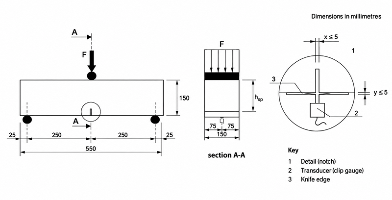
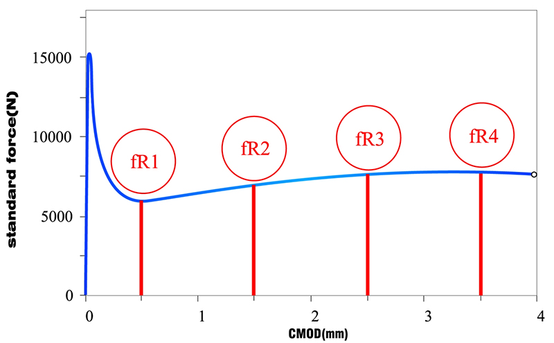
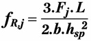
This is one of the principal strengths of the test: residual flexural strength can be related directly to defined crack and incorporated into established FRC design approaches. As the beam is loaded, the load carried by the specimen is recorded as the crack progressively opens. Residual flexural tensile strength is then determined at four defined crack openings:
fR1 at CMOD = 0.5 mm
fR2 at CMOD = 1.5 mm
fR3 at CMOD = 2.5 mm
fR4 at CMOD = 3.5 mm
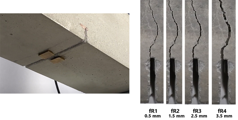
The principle of the test is relatively simple: the concrete is cracked, the crack is opened to a defined width, and the remaining load carrying capacity is measured at that point.
The four residual strength values provide engineers with several defined points along the post crack response rather than a single overall measure of performance, making it valuable for structural design, specification or material comparison. However, forcing the crack through a predetermined cross section means the result can be influenced by the number and orientation of fibres intersecting that section. Unlike an unnotched specimen, the crack cannot develop naturally along a path of lower resistance elsewhere in the beam.
The relatively small fracture area can therefore make individual results sensitive to local variations in fibre distribution and orientation, with a favourable concentration or alignment of fibres at the fracture plane potentially producing a result that is not representative of the wider reinforced volume. The same phenomenon can also cause significant dispersion between beams with the same fibre dosage
Its strength as a controlled material characterisation test is also its principal limitation. The test describes the behaviour of one controlled crack through a relatively small section. It does not attempt to reproduce the multiple cracking, load redistribution or larger deformations that may occur within a full structural element.
ASTM C1609 Four Point Bending Beam Test
Post crack strength is determined at defined beam deflections, commonly L/600 and L/150, where L represents the test span. For the standard specimen sizes, these correspond to deflections of approximately 0.5 or 0.75 mm at L/600 and 2.0 or 3.0 mm at L/150, depending on the specimen and span (300 mm or 450 mm) used.
The residual flexural strength at a specified deflection can be calculated from the measured load using:
f = PL / bd²
where f is the residual flexural strength, P is the measured load at the specified deflection, L is the span length, b is the specimen width and d is the specimen depth.
The principle behind the calculation is straightforward: the beam is allowed to crack and deform, and its remaining load carrying capacity is measured at defined points after cracking.
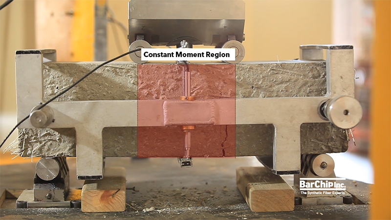
This can be considered both a strength and a limitation of the method. The specimen has greater freedom to develop its own failure location, but the resulting crack position and fibre population crossing that crack can introduce additional variability when comparing individual specimens.
The fundamental difference between the two common beam methods lies in how post crack deformation is defined and controlled. EN 14651 characterises residual strength at specified crack mouth opening displacements (CMOD), which can also be related to equivalent beam deflections, while ASTM C1609 characterises residual performance only at specified beam deflections. Both provide useful material characterisation, but neither should automatically be assumed to reproduce the behaviour of a larger structural element.
ASTM C1550 Round Determinate Panel Test
T = ∫ P dδ
where T is the energy absorbed, P is the applied load and δ is the central deflection.
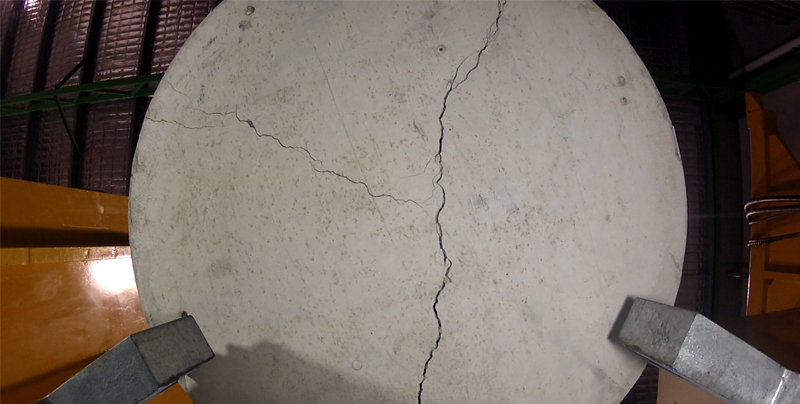
Rather than measuring the strength at a single point, ASTM C1550 considers the load carried over a defined deformation range, typically 5, 10, 20 or 40mm. The more load the panel continues carrying as it cracks and deflects, the greater the area under the curve and the greater its measured toughness. The larger panel and multiple fracture lines allow fibres distributed across a much greater area to contribute to the post crack response than in a beam test. Local variations in fibre distribution still influence performance, while the result is less dependent on the fibre population crossing a single fracture section. This makes ASTM C1550 particularly useful for applications in which significant deformation and load redistribution can occur after cracking, including fibre reinforced shotcrete and ground support.
EN 14488-5 Square Panel Test
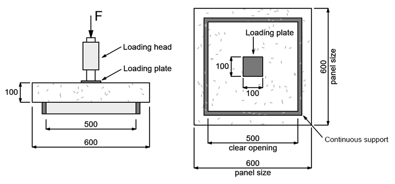
As the load increases, cracks develop through the panel and the fibre reinforcement bridges these cracks, allowing the specimen to continue carrying load as deformation increases. The support arrangement creates a statically indeterminate system in which loads can redistribute as cracking develops. The test records the load carried by the panel as a function of its central deflection. Toughness is determined by the area under the load-deflection curve, representing the energy absorbed by the panel as it cracks and deforms. The result is expressed in Joules (J). The calculation is:
T = ∫ P dδ
where T is the energy absorbed, P is the applied load and δ is the central deflection.
This behaviour is particularly significant for sprayed concrete, where cracking, deformation and interaction with the surrounding ground allow stresses to redistribute through a tunnel or mining lining. The larger specimen and distributed cracking make the square panel valuable for evaluating post crack behaviour. Specimen preparation, handling and testing are considerably more demanding than for beam tests and generally more difficult to produce than the ASTM C1550 round panel.
Both EN 14488-5 and ASTM C1550 therefore measure toughness through energy absorption, but they use different panel geometries and support conditions. Results from ASTM C1550 and EN 14488-5 are commonly correlated using an empirical conversion factor, with EN 14488-5 energy absorption at 25 mm taken as 2.5 times the ASTM C1550 result at 40 mm.
Barcelona Test – UNE 83515
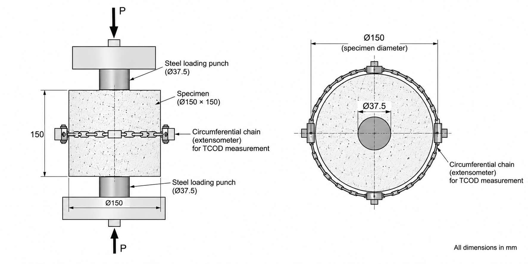
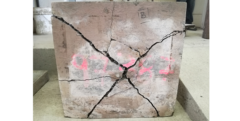
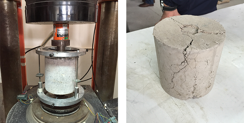
The resulting circumferential deformation is measured as Total Circumferential Opening Displacement (TCOD), allowing cracking strength, residual tensile behaviour and toughness to be characterised. The multiple fracture surfaces allow a larger population of fibres to influence the result than the single fracture plane of a notched beam. Toughness can be represented as the area under the load-TCOD curve:
T = ∫ P d(TCOD)
where T is the energy absorbed, P is the applied load and TCOD is the Total Circumferential Opening Displacement.
In simple terms, the more load the specimen continues to carry as the radial cracks open, the greater its measured toughness.
A major practical advantage of the Barcelona test is the specimen itself. Cylinders are easier to manufacture, transport and handle than panels, while the test can be performed using conventional compression testing equipment. Specimens can also be obtained from cores, making the test useful for quality control and assessment of completed construction. The stress state is more complex than in conventional flexural testing, and the resulting parameters do not directly correspond to the residual flexural tensile strengths specified in EN 14651.
Where a design method requires EN 14651 residual strengths, Barcelona test results require an appropriate validated relationship before they can be used.
Other Test Methods of Fiber Reinforced Concrete
A number of other test methods have been developed to characterise fibre reinforced concrete.
JSCE-SF4 (Japanese Concrete Standard) uses an unnotched beam under third point loading and evaluates flexural toughness from the area under the load deflection curve. The method has been widely used historically for FRC and has contributed to the development of subsequent beam testing approaches.
ASTM C1399 was developed to determine the average residual strength of fibre reinforced concrete beams after cracking. It provided a useful method for comparative material evaluation and quality control, although the standard was withdrawn in 2024 and ASTM C1609 now provides a more current basis for flexural performance testing.
Montvideo Test (MVD) is a simplified wedge splitting test developed as a practical quality control method for fibre reinforced concrete. Using small specimens or cores, the test measures post crack behaviour without the specimen size and handling requirements of conventional beam tests. Results can be correlated with EN 14651 residual strengths, providing a practical way to verify production concrete against an established performance benchmark.
Other specialised methods, including direct tensile, wedge splitting and double edge wedge splitting tests, are primarily used in research or specialised material characterisation. Direct tensile testing is theoretically attractive because it measures the property of greatest interest directly but achieving stable and repeatable post crack tensile testing is considerably more difficult than performing indirect flexural or panel tests.
For most practical FRC applications, the major beam, panel and indirect tensile tests therefore remain the most useful methods of characterisation.
Choosing the Right Test
Where structural design models require residual tensile properties, beam tests such as EN 14651 and ASTM C1609 provide defined parameters at specific stages after cracking. Where substantial cracking, deformation and load redistribution are important, toughness testing can provide valuable information about energy absorption across a broader post crack response.
This distinction is particularly relevant to fibre reinforced shotcrete used for tunnel and mining ground support, where a lining may continue carrying load as the surrounding ground deforms. Panel testing can capture multiple cracking and load redistribution across a larger specimen, while beam testing provides controlled residual strength parameters that may be required for design or specification.
The appropriate FRC test is therefore determined by the application and the engineering question being asked. A test result is meaningful only when the property being measured is relevant to the behaviour of the structure.