Innovative Use of Fiber Reinforced Shotcrete on the North Strathfield Rail Underpass- Sydney, NSW
The first use of macro synthetic fibre reinforced ground support in a rail tunnel in Australia.
Downloading the paper, “The North Strathfield Rail Underpass- Driven Tunnel Design and Construction” – M Gonzalez, M Kitson, D Mares, B Muir, T Nye, and T Schroeter.
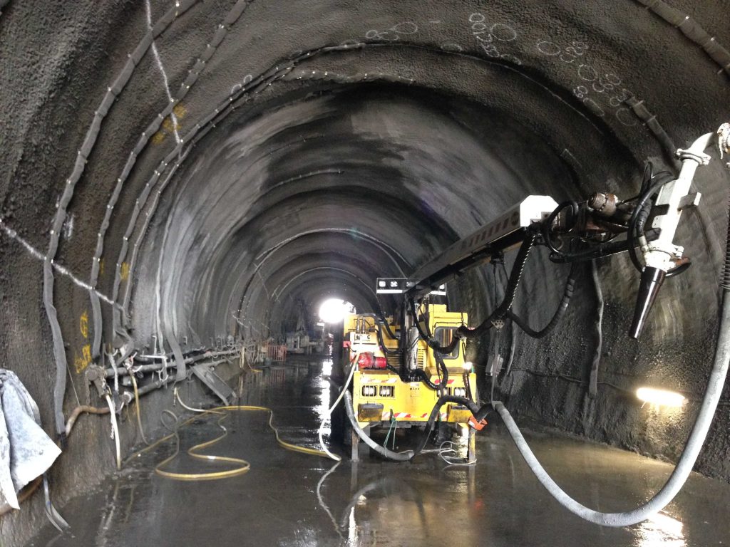
The North Strathfield Rail Underpass tunnel in Sydney, Australia, is a 148m long rail tunnel designed for freight trains up to 1.5km in length. While short, the tunnel required and includes numerous technical innovations and takes full advantage of the benefits offered from Barchip’s fiber reinforced shotcrete. The 9m wide, arched roof single tunnel was excavated by a road header underneath operational passenger and freight railway lines with a maximum cover of 3m.

The project was delivered by the NSRU Alliance (TfNSW, John Holland and Bouygues). The lead designers were the DJV of SKM and PB with Mott Macdonald the designer of the driven tunnel discussed here.
The tunnel has a maximum ground cover of 3m, consisting of track ballast overlying fill and shale rock which is weathered near the surface. The permanent ground support in the tunnel consists of a 250mm thick Barchip macro synthetic fiber reinforced single pass (wet mix) sprayed shotcrete lining. Steel canopy tubes drilled ahead of the tunnel face provide the initial ground support ahead following the shotcrete lining. No steel sets or lattice girders were used on this project. The design is based on an arched profile ensuring that the fiber reinforced shotcrete itself is always in compression under both dead and live loading. Barchip’s macro synthetic fibers in the initial structural shotcrete lining have four functions;
- To minimise shrinkage cracking within the shotcrete lining.
- To provide residual strength and redistribute stresses within the lining.
- Are environmentally friendly and will not deteriorate over the 100-year life of the tunnel.
- The final shotcrete layer is 100mm in thickness using micro synthetic fibers to reduce spalling in the event of a fire. Although macro fibers were not specifically used for fire and are not as effective as micro fibers for this purpose, the underlying macro synthetic fibers in the structural shotcrete layer will also help to reduce spalling in the event of a fire.
[et_bloom_inline optin_id=”optin_4″]

The tunnel excavation was completed with no distribution to the railway operations above. Some additional facts are;
- The construction method used 12m long grouted steel canopy tubes and approximately 35no., 12m fiberglass dowels across the face followed by incremental excavation, which were carried out in 1.3m to 1.5m lengths with shotcrete built up in multiple layers immediately behind the tunnel face. A new array of canopy tubes and pattern of face dowels were installed every 9m length of tunnel with a minimum of 3m overlap.
- Shotcrete 3m back from the face was approximately 250mm thick and at the face 150mm thick before the next excavation cycle. Shotcrete at the face had to have a minimum strength of 6MPa before commencing the next excavation cycle.
- Canopy tubes and fiberglass dowel installations were staggered at 4.5m intervals to allow the following shotcrete lining additional time to gain strength and to ensure there was always support at the face (with overlaps of the canopy tubes and dowels).
- The original concept (by others) was a cut and cover tunnel design but the ability to close active commuter rail lines for construction times little more than 4 weekends per year would have resulted in a construction period extending over many years compared to the driven tunnel which was excavated in 8 months.
- Train operators have no control over the freight train cargo content and as such the tunnel was designed to withstand a 4-hour hydrocarbon fire with significant loss of the shotcrete lining thickness.
- There is no mechanical plant in the tunnel itself to maintain. There is a low point tunnel sump in the dive structure at the northern portal of the tunnel.
Without applying some innovation, firstly by adopting a driven tunnel rather than the cut and cover option, this tunnel would have been more difficult to construct (the tunnel alignment was also moved 60m north from the original alignment to site in better geology). Once the driven tunnel had been selected the opportunity to apply innovations to the driven tunnel was then intitiated.

