Full-Scale Testing of BarChip
Fibre Reinforced Concrete Tunnel Segments
Part 3 – Flexural Testing
Who says you can’t use macro synthetic fibre in precast concrete tunnel segments?


We keep hearing it, and reading it – “you can’t use macro synthetic fibre in precast concrete tunnel segments”. To prove this is wrong, BarChip engaged the engineering team at the University of Brescia to conduct full-scale testing of BarChip fibre reinforced concrete tunnel segments. The objective was clear, prove that BarChip was suitable for use in precast tunnel segments according to the design requirements of:
- A known tunnel, and
- The Model Code 2010
Full-scale segments using 3 different reinforcement systems were tested in flexure to simulate temporary loading conditions. The results of the study speak for themselves.
- BarChip is a suitable material for precast concrete tunnel segments
- BarChip does adhere to design standards, and
- BarChip can deliver the required performance of precast tunnel segments
Full-Scale Flexural Testing of BarChip Fibre Reinforced Precast Concrete Tunnel Segments
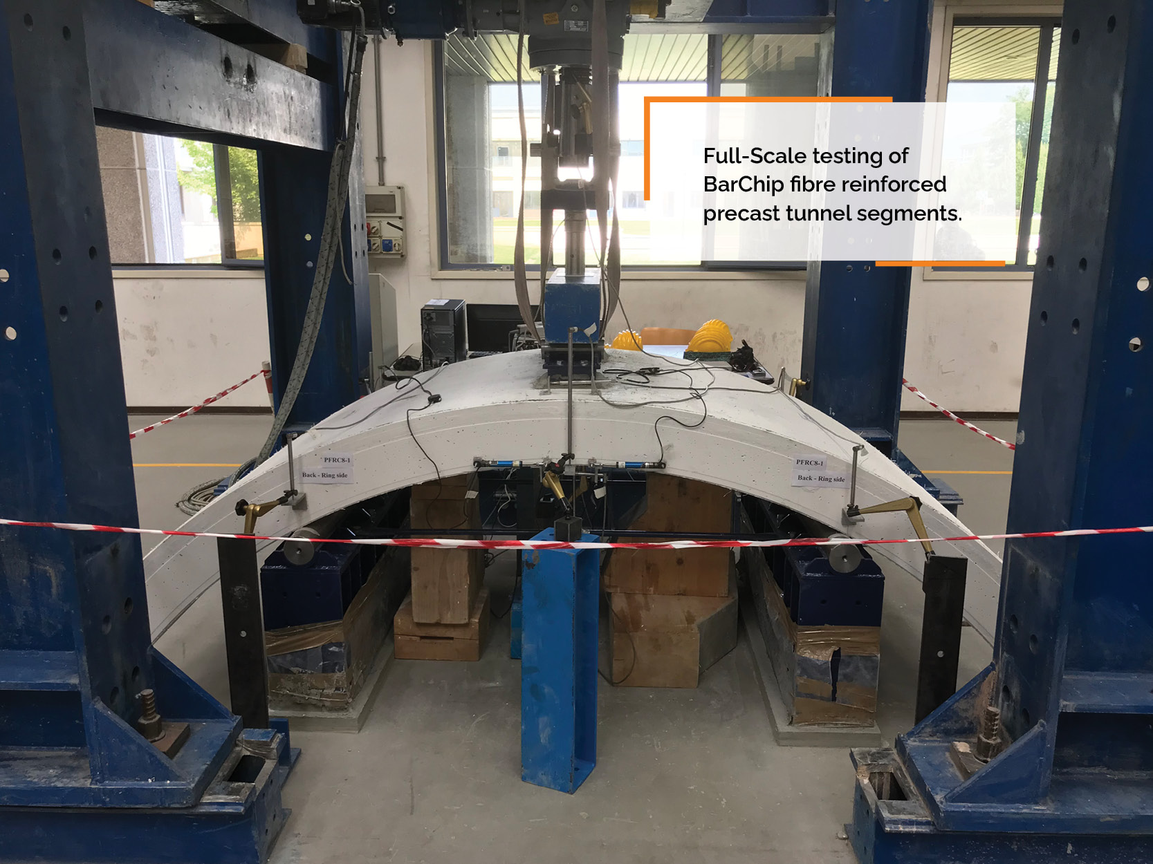
For the test set-up, a three-point bending configuration was adopted, characterized by a net span of 1600 mm. Two supports were continuous along the entire segment width, while the load was applied at segment extrados by means of two steel plates (150 x 200 mm) placed on a layer of high-strength mortar (to guarantee a uniform contact). To ensure a good distribution of the load along segment width, a stiff steel girder was adopted between the electro-mechanical actuator (loading capacity of 500 kN) and the steel plates. A displacement-controlled procedure was used, measuring the applied load by means of a load cell (Figure 1, 2). The flexural tests were carried by using a quasi-static loading rate of 0.3 mm/min.
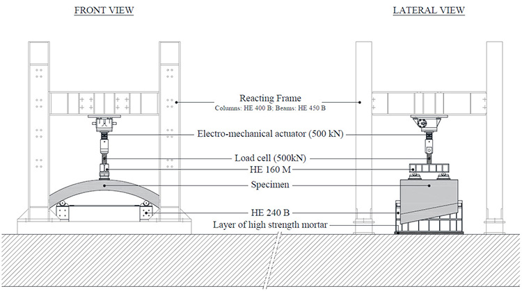
Figure 1: Scheme of loading system adopted (three-point bending test).
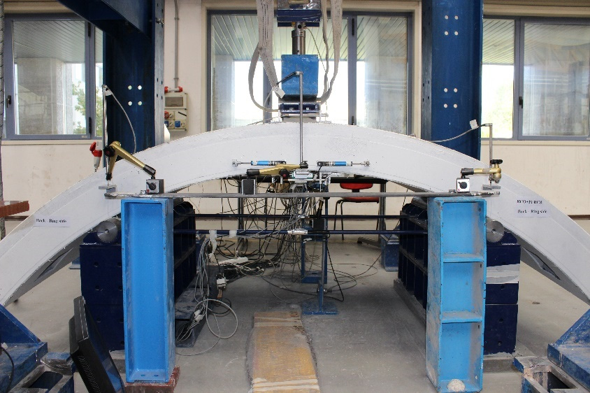
Figure 2: Full-Scale flexural testing of BarChip fibre reinforced tunnel segments
Figure 3 shows the instrumentation details. Three Linear Variable Differential Transducers (LVDTs) were placed on segment intrados to measure the mid-span deflection at segment centre (D3) and sides (D1 and D2). Moreover, the local displacements of supports were measured by means of four LVDTs placed at the sides of each support (D4, D5, D6, D7,); consequently, the actual mid-span deflection was evaluated by considering the vertical settlements at supports. The flexural crack opening at the maximum bending moment was measured by means of two Potentiometric Transducers (PTs), identified as W1 and W2.
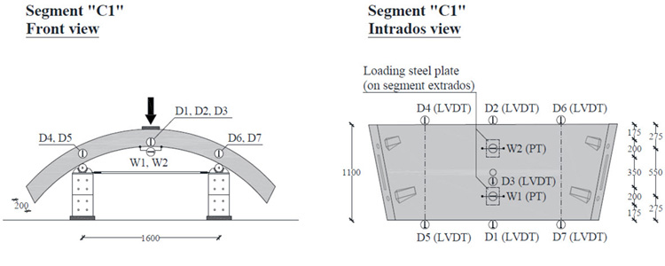
Figure 3: Details of test set-up and instrumentation (mm)
Material Companion Testing
During segment casting, for each concrete batch six 150x150x150 mm cubes were produced for compressive strength testing. For the BarChip only and Hybrid solutions, six 150x150x600 mm beams were produced to determine mechanical properties in accordance with EN 14651. Samples were tested together with the full-scale segments at 58-days.
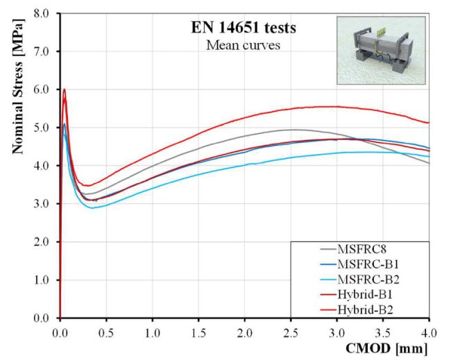
Fig 4: Experimental results of bending tests on MSFRC beams, MSF-B1 & B2, HYB-B1 & B2 according to EN14651.
Sample testing showed that BarChip provided significant structural performance at both the Serviceability Limit State (SLS, crack width range up to 0.5 mm) and Ultimate Limit State (ULS, crack width range up to 3 mm). All samples reinforced with BarChip48 showed very similar post cracking behaviour. Figures 4 also shows the similarity to results of MSFRC8 from the previous mechanical characterization research, underlining the consistent flexural performance and repeatability of the FRC results throughout the tests.
Experimental Results of Full-Scale Tunnel Segment Testing
Figures 5 shows the results of the full-scale flexural testing in terms of load vs. mid-span net deflection curves for the segments out to 15 mm. According to the adopted test set-up, the corresponding requirements for ULS (11.45 kNm) and SLS (8.81 kNm) was determined to be an ultimate load of 28.6 kN and service load of 22.0 kN, which are shown as dotted lines on the graphs. Detailed results are shown in Table 2.
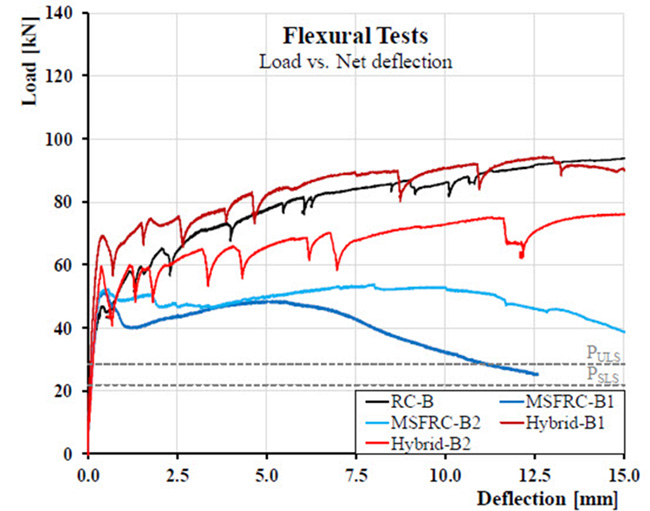
Figure 5: Flexural tests for: RC-B, MSF-B1, MSF-B2, Hybrid-B1, Hybrid-B2 segments; experimental curves of load vs. mid-span net deflection up to 15 mm.
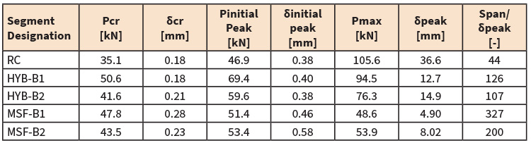
Table 2: Experimental results of flexural tests
Steel Rebar Cage Reinforced Segments
The RC Segment performed in a typical manner to rebar reinforced segments. First crack occurred at 35.1 kN, increasing to a flexural initial peak of 46.9 kN and maximum peak load of 105.6 kN. However, at 80 kN crack widths increased significantly. In total 8 cracks formed, six along the entire segment and 2 not developing completely. No cracking was present at the nominal service load or ultimate load.
Hybrid Segments
Both Hybrid segments show a similar behaviour to the full cage segments at larger displacements and a superior behaviour at smaller displacements, which is excellent performance considering there is 50% less longitudinal curved rebar and 68% less steel in total. Due to the contribution of fibres, the first-peak load of the Hybrid Segments were significantly higher as compared to the RC segment. Both segments produced a significant increase from first peak load to maximum load, with HYB-B1 increasing 86% and HYB-B2 83%.
The crack pattern of both segments was similar to the RC Segment, demonstrating again the similar flexural behaviour. No cracking was present at the nominal service load or ultimate load.
BarChip MSF Segments
BarChip MSF-B1 and BarChip MSF-B2 exhibited first cracking approximately 23% and 30% higher than the RC Segment, with no significant load drop at low displacement. BarChip MSF-B1 produced first peak load of 47.8 kN, increasing to 51.4 kN at initial peak load and decreasing to 48.6 kN max initial peak load. BarChip MSF-B2 produced a first peak load of 43.5 kN, increasing ~20% to 52.4 kN at initial peak load and increasing again to 53.9 kN max initial peak load. The increase in initial peak load from peak load in both segments can be considered good mechanical behaviour.
It is possible to explain the improved ductility of BarChip MSF-B2 through analysis of the crack pattern. Cracking in BarChip MSF-B1 localised into a single crack earlier in the deformation. BarChip MSF-B2 exhibited a more spatial distributed crack pattern, with two flexural cracks developed across the entire segment (Figure 6), a result many have said is not possible with macro synthetic fibre reinforcement. No cracking was present at the nominal service load or ultimate load.
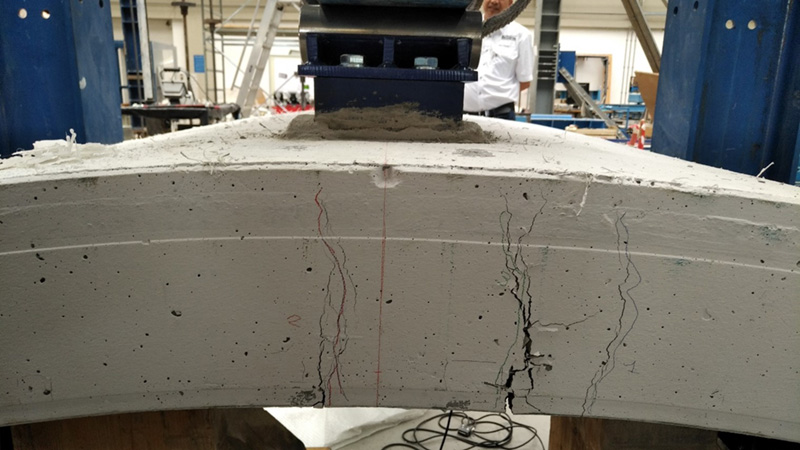
Figure 6: Multiple cracking in BarChip fibre reinforced tunnel segment tested in flexure.
The BarChip segments presented a significantly less pronounced peak load drop than those exhibited by the beam samples tested according to EN 14651, which is a result of different cross-sectional widths. In a precast tunnel segment, stress redistribution takes place along the entire width (1100 mm), whereas standard notched samples present a very small specific failure area of 150 x 125 mm2.
This shows that the performance of macro synthetic fibre in standard beam tests significantly underestimates the actual in-service performance, especially in statically indeterminate structures such as precast tunnel segments.
Finally, as for RC and Hybrid specimens, it should be underlined that both MSF segments were characterized by a first crack load Pcr significantly higher than the design bending moment; therefore, at the nominal design load, no cracks are to be expected.
Conclusions
- BarChip 48 macro synthetic fibre reinforcement can be considered suitable for structural purposes in tunnels according to fib Model Code 2010
- The fibres can be successfully used to substitute the minimum amount of shear reinforcement and to satisfy the flexural requirements of MC 2010
- BarChip fibre reinforced segments and hybrid segments met the performance requirements of the reference tunnel.
- Fibre reinforced segments yielded higher flexural cracking load than the RC segments (full cage)
- Hybrid segments provided a flexural capacity remarkably similar to the RC segments while using 70% less steel reinforcement.
If you want to discuss the results in more details contact us at info@barchip.com.
Follow the links below to review the testing in more detail.
- BarChip Tunnel Segment Testing Part 1 – Introduction, Reference Tunnel & Reinforcement Solution
- BarChip Tunnel Segment Testing Part 2 – Material Mechanical Characterisation (Beam Testing & Concrete Mix Design)
- BarChip Tunnel Segment Testing Part 4 – Full-Scale Point Load Testing (coming soon)